The Motor Couplings position connected exploded assembly diagram
STEP1. The arrows indicate the four screws, as shown above (1) at <1>, unscrew to remove.
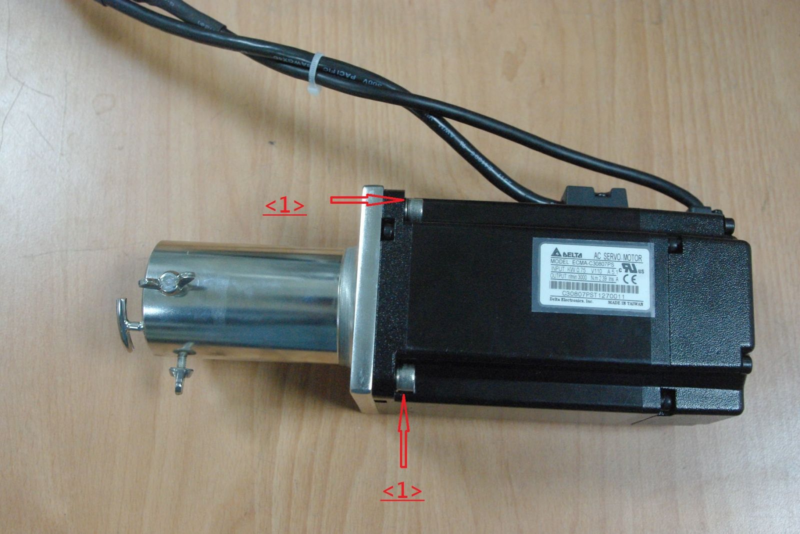
【Caption 1】
STEP2.Figure (2) indicated by the arrow at <2> screws unscrew removed.

【Caption 2】
STEP3. Make sure the screws placed in the keyway, as shown in (3) arrows indicate <3>
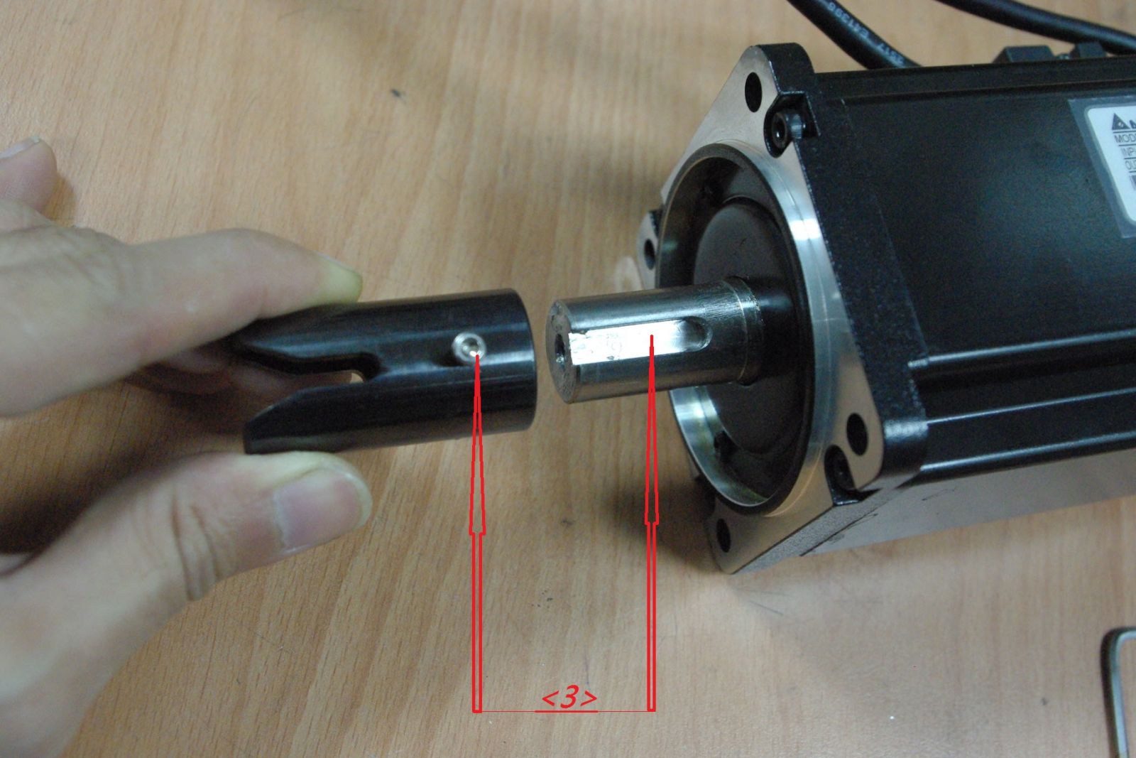
【Caption 3】
STEP4. Couplings and motor seat take the distance A (see Figure 4a), the distance A is equal to 340 (mm) - to disk drive seat Cross center distance B (see Figure 4b), the locking screws
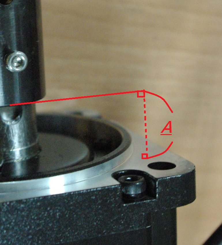
【Caption 4-a】
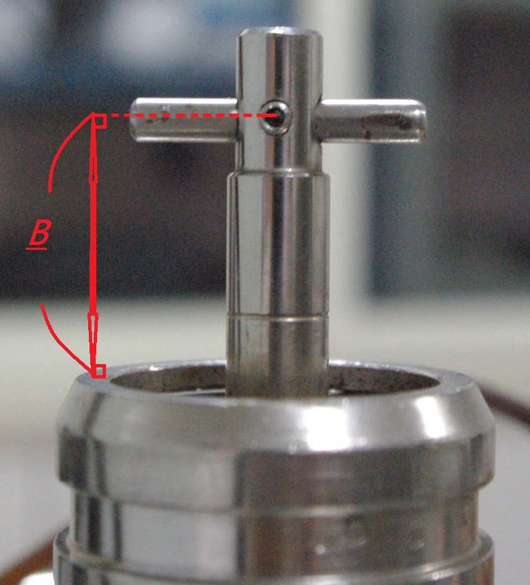
【Caption 4-a】
STEP5. Qi Mada seat front (at the arrow indicates <5>) and the motor holder (arrow directions at <6>) of the same side.
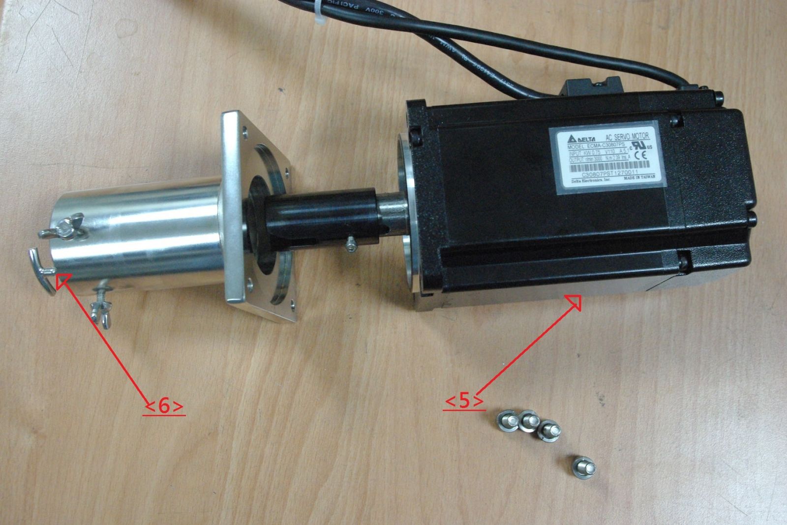
【Caption 5】
STEP6. Tightened on (6) arrows indicate at <1> four screws.
【Caption 6】
<All rights reserved. Do not copy or quote with authorization.>